How to Check Garage Door Sensor Wiring
Learn to safely inspect and test your garage door sensor wiring, identify misalignment or damaged cables, and restore reliable door operation with a clear, homeowner-friendly step-by-step guide.

Goal: verify that the garage door safety sensor wiring is connected correctly and signaling properly. You’ll inspect sensor alignment, test the wiring for continuity, and ensure the connector housings are intact. This quick check helps prevent accidental door closure on people or objects and can save you a trip to the repair shop. Tools you’ll need: flashlight, basic multimeter, small screwdriver, and a stable ladder. If you spot frayed wires, damaged insulation, or erratic readings, stop and seek professional help.
Why sensor wiring matters for garage doors
Sensor wiring is the lifeline of modern garage doors, translating safety signals from the photoelectric eyes to the opener. When wiring is damaged, misrouted, or poorly connected, the door may fail to stop or reverse, creating a serious safety hazard. According to GarageDoorAdjust, understanding the wiring path — from the control board to each sensor and back — helps homeowners diagnose issues quickly and safely. This block lays the groundwork for a reliable check by outlining what you’re protecting and why a careful inspection matters for daily use. You’ll learn where to look, what to test, and how wiring quality influences sensor reliability and door performance over time.
Safety first: plan before touching wires
Put safety at the forefront before you begin any inspection. Disconnect power to the opener at the circuit breaker and unplug the unit if possible. Use a non-contact voltage tester to confirm no live current is present on exposed conductors. Keep children and pets away, wear eye protection, and work on a dry surface. If you feel unsure at any time, pause and consult a licensed technician. GarageDoorAdjust emphasizes that safer, slower work reduces the risk of shock or inadvertent door movement during testing.
Tools and materials you’ll use
Before you start, assemble a small toolkit to keep the job smooth and safe. You’ll need a flashlight for dim corners, a multimeter for continuity checks, insulated screwdrivers, wire strippers, electrical tape or heat shrink, a ladder or sturdy step stool, and spare wire connectors. Having a spare sensor or replacement wire handy can save time if you discover a damaged component. Use items with clearly labeled quantities to avoid confusion during the test.
Visual inspection: mounting and wiring paths
Begin with a thorough visual scan of both safety sensors, their mounting brackets, and the wires that run between them and the control unit. Look for cracked housings, loose fasteners, pinched cables, and evidence of wear near corners or where wires bend. Note any red flags such as exposed copper, melted insulation, or frayed strands. Good routing matters: wires should follow factory channels away from moving parts, not across hot surfaces or sharp edges. Documenting these observations helps you decide whether a repair is within DIY reach or if a pro should intervene.
Sensor alignment and signal indicators
The sensors must face each other directly with a clear line-of-sight. Misalignment can trigger false alarms or failure to detect obstructions. Check alignment marks on the brackets, verify the LEDs (if present) show proper signaling when the door is tested in the down position. If the sensors look misaligned, adjust them in small increments and retest. A misaligned pair can mimic wiring faults, so confirm both physical and electrical alignment to pinpoint the root cause.
Isolating power safely
Power isolation is essential for any wiring work. Turn off the opener, switch off the corresponding circuit breaker, and disconnect any batteries if your model uses them. Use the multimeter to confirm no residual voltage on exposed conductors. When you’re comfortable that the circuit is truly dead, you can proceed with inspection and testing. This step minimizes the risk of electric shock and prevents the opener from moving while you’re handling wires.
Continuity testing with a multimeter
Continuity testing confirms whether the circuit path from the control board to each sensor is intact. Set your multimeter to the continuity or low-resistance setting, and place probes on the sensor’s two conductors at the connector end. A near-zero resistance reading typically indicates a good connection; a high or infinite reading suggests a broken wire or bad connection. Repeat on both sensors and at the control board terminals. If you see inconsistent results, test the entire path, including any splice points and inline connectors.
Tracing wire paths and detecting wear
Trace each conductor from the control unit out to the sensor, following the entire route. Look for brittle insulation, worn sheathing, or areas where cables rub against metal or moving parts. Any kinked or pinched wiring warrants replacement or rerouting. If the wire runs through conduit, check for cracks or gaps in the conduit that could expose wires to damage. Document trouble spots and plan targeted repairs rather than a full replacement if only isolated sections are affected.
Reconnecting, resealing, and securing
If you found damaged connectors, replace them with similar rated parts. Reconnect wires to sensor terminals using the same color order as the original configuration. Use heat-shrink or electrical tape to seal splices and protect against moisture intrusion. Re-secure the wiring harness with cable ties, keeping bundles away from hinge areas and moving components. Once reconnected, gently tug on wires to confirm solid connections without excessive strain.
Functional test: verify door behavior after wiring changes
Power up the system and run a controlled door test. Close the door with the sensor path unobstructed; then briefly place a non-dangerous object (like a cardboard cutout) in the sensor beam to confirm the door stops or reverses. If the door behaves correctly, reattach any covers and re-check operation at various speeds. If the door continues to ignore safety signals, recheck all connections, or consider replacement of the sensor unit.
Common faults and quick fixes you’ll likely encounter
Typical issues include unplugged connectors, loose sensor screws, misaligned brackets, and damaged insulation. In many cases, reseating the connectors or realigning the sensor resolves the problem. If you consistently observe erratic sensor signals after a test, it may indicate a failing sensor or a damaged wire harness that requires replacement. Keep a repair log and compare notes after each fix, which helps you notice patterns over time.
When to call a pro and what to expect
If you identify frayed or submerged wires, signs of burning, or persistent sensor errors after a thorough DIY check, stop and contact a licensed technician. The GarageDoorAdjust team recommends professional service for electrical repairs that involve wiring inside the opener housing or control board, as improper wiring can affect overall safety. A pro can test with specialized equipment, replace compromised components, and confirm code-compliant wiring.
Authority sources for safe wiring checks
For authoritative guidance on electrical safety and safe repair practices, consult: OSHA at https://www.osha.gov, Consumer Product Safety Commission at https://www.cpsc.gov, and the National Institute of Standards and Technology at https://www.nist.gov. These sources provide general safety standards that align with best practices for DIY garage projects and underscore why careful checks of sensor wiring matter for long-term door reliability.
Tools & Materials
- Flashlight(Bright beam to inspect dim corners)
- Multimeter(Continuity/voltage testing; prefer auto-ranging)
- Insulated screwdrivers(For safe terminal work)
- Wire strippers(Strip insulation cleanly without nicking conductors)
- Electrical tape or heat-shrink tubing(Seal and protect splices)
- Non-contact voltage tester(Quick live-check before handling wires)
- Replacement connectors and sensors (if needed)(Have compatible parts on hand)
- Ladder or stable step stool(Access sensors safely)
- Gloves and safety glasses(Personal protection)
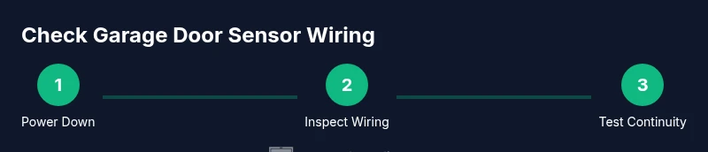
Steps
Estimated time: 45-60 minutes
- 1
Power down and secure the area
Turn off the opener at the wall control and unplug the unit if possible. Use a lockout or tag to indicate work in progress. This prevents the door from moving unexpectedly while you inspect wiring.
Tip: Double-check with a non-contact tester after unplugging to confirm no live voltage. - 2
Access sensor wiring and plan routes
Open sensor covers and identify the two conductors from each sensor to the control board. Note the color coding; maintain consistent connections during any rework. Avoid bending wires sharply.
Tip: Take photos from multiple angles before touching anything for reference. - 3
Inspect physical condition of sensors
Look for cracked housings, loose mounting screws, and worn insulation. If you see exposed copper, stop and replace affected wires. Damaged sensors can give false readings regardless of wiring.
Tip: Use a flashlight to catch hairline cracks you might miss in ambient light. - 4
Test sensor alignment visually
Confirm that the sender and receiver face each other directly with a clear beam. Misalignment can mimic wiring issues and cause a failure to detect obstructions.
Tip: If the LEDs indicate misalignment, small adjustments can correct many problems. - 5
Isolate power again before wiring checks
Reconfirm the system is de-energized to avoid shocks while touching terminals or connectors. This is a safety-critical step before any testing.
Tip: Label the circuit breaker to remind future users of the work performed. - 6
Check continuity with a multimeter
Set the meter to continuity, and probe across each sensor wire at both ends. A near-zero reading typically confirms a solid path. Do this for both sensors and the control board connections.
Tip: If readings drift, check for loose connectors or corrosion on terminals. - 7
Trace and assess wire routing
Follow wires along their paths to detect kinks, pinches, or potential abrasion points. Replace or reroute damaged segments and re-secure wiring away from moving parts.
Tip: Use protective conduits or clamps to prevent future wear. - 8
Reconnect and reseal connections
Reattach wires to their connectors in the original color order. Seal splices with heat shrink or electrical tape and secure with ties so nothing shifts during operation.
Tip: Avoid over-tightening screws that could crack the plastic housings. - 9
Power up and perform a functional test
Restore power and run a controlled door test with the sensor beam unobstructed. Introduce a temporary obstacle to verify the door stops or reverses as expected.
Tip: Test at different door speeds to ensure consistent sensor response.
Got Questions?
How can I tell if the sensor is properly aligned?
Look for direct face-to-face alignment between the two sensors and confirm LED indicators or test results show stable signaling. If the beam is misaligned, adjust the sensor brackets slightly and retest.
Check alignment by ensuring the two sensors face each other squarely and use a test to confirm proper signaling. If misaligned, adjust and retest.
Do I need to disconnect power to run the continuity test?
Yes. Always power down and unplug the opener before handling wiring or testing with a multimeter to avoid shock or accidental door movement.
Power down and unplug the opener before testing to stay safe.
What resistance reading indicates a good wire path?
A near-zero resistance on continuity testing typically indicates a solid path. Very high or open readings suggest a broken wire or bad connection that needs attention.
Near-zero resistance means good continuity; high resistance means there may be a break.
Can damaged sensors be repaired or must they be replaced?
Minor connector or cabling wear can sometimes be repaired, but damaged sensor housings or broken beams usually require replacement for reliable operation.
Small fixes may work, but often sensors need replacement for safety.
When should I call a professional?
If you encounter burn marks, exposed conductors, or repeated sensor faults after a DIY check, stop and hire a licensed technician. Electrical work inside the opener requires expert handling.
Call a pro if you see burns, exposed wires, or persistent faults after your check.
Is it normal for sensors to emit a faint glow or LED during testing?
Many sensors use status LEDs; a consistent, stable indication is normal. If the LED flickers or stays off, recheck alignment and wiring.
A steady LED is normal; flickering or off means recheck alignment or wiring.
Watch Video
Quick Summary
- Plan safety-first; disconnect power before touching wires.
- Inspect both wiring paths and sensor alignment for reliable operation.
- Use a multimeter to confirm continuity across sensor circuits.
- Secure and seal connections to prevent future wear.
- If faults persist, consult a professional and avoid risky DIY wiring.